
We are using the hilti software to design some anchors. We have perform a CBFEM design to take in consideration that loads in anchors can be higher due the plate thickness. During the calculations, the concrete bearing is too high due the very small contact area taking in Account. Also, the stresses in the concrete are given which dont match with the stresses calculated with the total compression load divided by the area. We think there is a mistake, please comment.
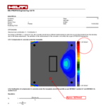
Dear Mr. Leiva
Thank you for your question.
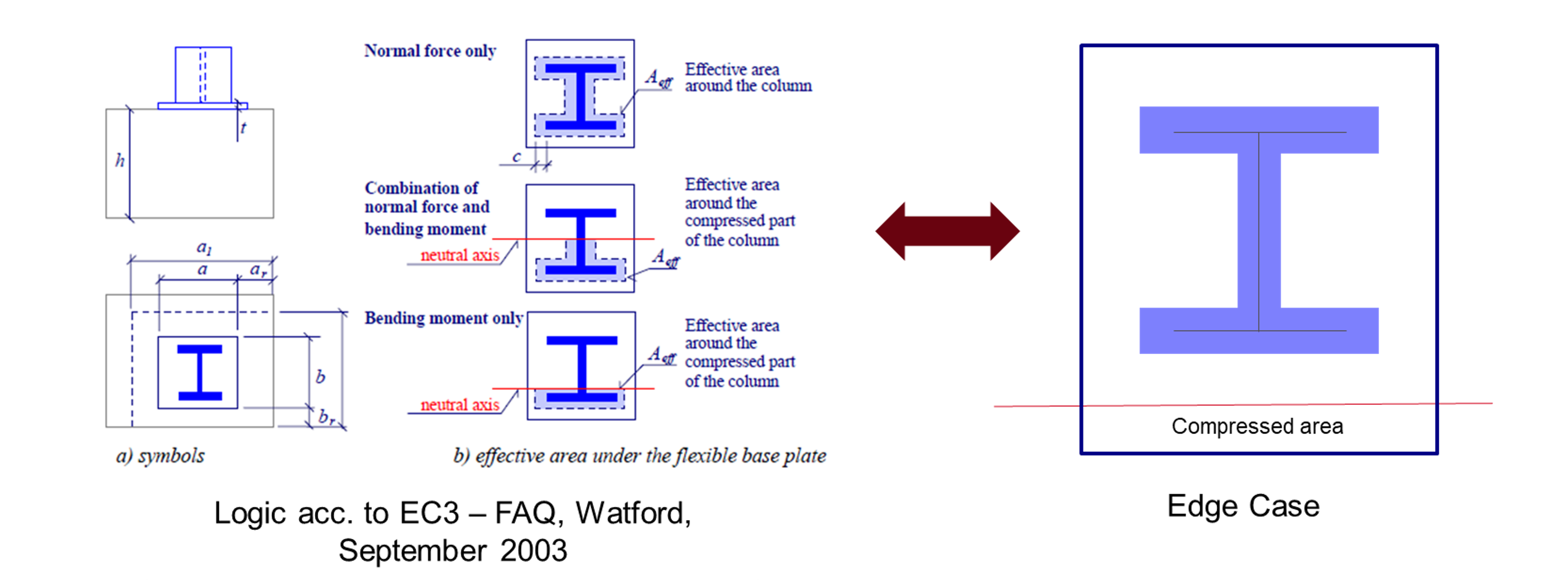
For steel-to-concrete joints, PROFIS Engineering uses the T-Stub method in EN1993-1-8 to assess base plates in compression.
This method is especially applicable for joint foundations in I-shape beams, where the compressed area near a compressed flange is taken into account.
The effective area of compression is the intersection of the total possible effective area around the collumn and the compressed part of the collumn.
However this approach can create some problems for edge cases, because e.g. in the picture on the right, acc. to EN1993-1-8, the Effective Area of compression is 0 which would lead acc. to the formula 𝜎=𝑁/𝐴𝑒𝑓𝑓 = ∞
When the intersection of the area is getting close to zero (e.g. small profiles, big plates), then this verification acc. To EN1993-1-8 is not working very well.
Furthermore, finite element are very sensitive to meshing, and small differences in input like C30/37. This doesnt change the overall load distribution results very much, but can lead to some small differences like an area of intersection varying of A_eff from 0 – 2%, which in turn create «nonesense» utilization results.
But how to deal with this issue of the intersecting compression and areas around the profile in real life?
In Hilti, we would be really interested in knowing how do engineers in Europe deal with this in real life, and perhaps change the verification for cases which are not foundations (would need to be explore).
E.g. in the US it is accepted to take the actual area of compression (Total compressed area under the plate) and determine the average stress in the compressed area, independent of the location of the profile.
If you have any questions, please do not hesitate to contact us here or at our e-mail address Planer-Support@hilti.com.
With kind regards
Your HILTI engineering consultancy
Thanks for your reply. I think the effective area to resist the compression should be taken from the software analysis (The bearing stresses are already given by the software). And the bearing capacity should be calculated according to EN 1992-1-1 section 6.7. The T-stub in EN-1993-8 is an example for a direct load path of the compression flange taking in account the base plate thickness and material grade which it is not valid in this case. Normally, the hilti software take the compression zone away from the member. If the design is done with a rigid plate, the design complies with the bearing capacity of the concrete but when it is flexible this issue appears. Based on the comments given, this should be a problem for rigid and flexible plates. What I will expect is higher stresses (Tension and compression zone) with the flexible plate due the smaller lever arm between compression zone and tension which it is correctly done by the software. Thus, I will recommend checking the Aeff calculated in the section 2.5.2 of the report which I believe there is a mistake.